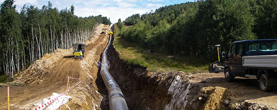
Stress-tests on the DN 1400 international gas pipeline GAZELLE
In the years 2011–2012 in our country the construction of the international pipeline DN 1400 GAZELLE was carried out – it was the first gas pipeline of this dimension that passes through the Czech Republic, which was put through stress-test in its full length. The pipeline runs from BDS (Border Delivery Station) Brandov to LVS (Line Valve Station) Přimda, the length is 155 km and it is operated at maximum pressure of 85 bar.
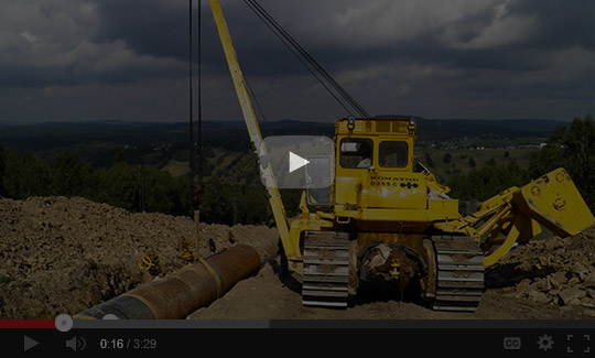
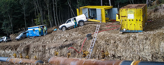
Gas pipeline DN 1400 GAZELLE in Krušné hory (The Ore Mountains)
The construction was divided into 3 LOTs. CEPS a.s. conducted in the second half of 2012 stress-tests and related activities at LOT 1B between BDS Brandov over LVS Jirkov and LVS Hrušovany to LVS Sýrovice in the length of 52.5 km.
On the pipeline leading over Krušné hory with a total elevation of almost 700 m were carried out processes of cleaning, calibration, stress-test and pressure test. At the end before the commissioning, the gas pipeline was dried up.
All activities were carried out in accordance with the Czech and also European regulations – ČSN EN 1594, ČSN EN 12327, TPG 702 04 and TPG 702 11.
By the enlargement of sections above normal limits we contributed to the acceleration of the pipeline construction
The pipeline was mainly in the mountainous parts professionally and carefully divided into sections so that all sections met the requirements for resulting MAOP (STOP), which were moving just above DP. The minimum STOP was 87.5 bar. This made possible to minimize the number of test sections while maintaining the required operating parameters.
The gas pipeline was divided into 21 sections, some of which were with regard to TPG 702 04 enlarged, namely up to twice as much. According to TPG 702 04 the maximum segment size allowed for this dimension is 6,000 m³ of the internal capacity; however the largest tested section had the capacity of 12,240 m³ at the length of 8,100 m, by which it exceeded the normative limit by more than 100%.
For this exemption it was necessary to acquire the positive standpoint of the future operator and subsequently the approval of the State Professional Supervision – Technical Inspection of the Czech Republic (TIČR).
The enlargement of sections, where it was technically feasible, allowed to considerably speeding up the test procedure, and thereby the whole construction.
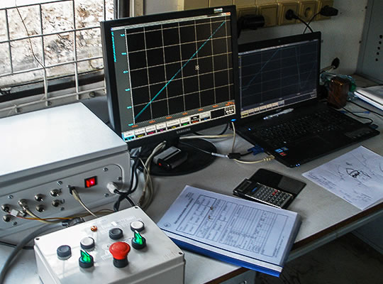
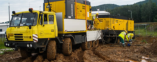
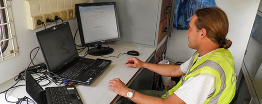
We secured the reliable tests’ control by the extremely precise measurement
As a counterbalance to enlargement of sections were used more accurate techniques of measurement. In the course of stress-test was carried out the continuous calculation of the integral volumetric deformation in a maximum of one-second intervals, thus the deformation behaviour of pipeline was under the constant supervision, and thereby to avoid exceeding of the deformation maximum.
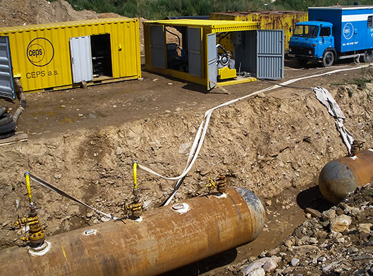
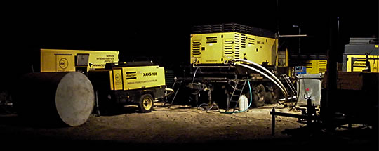
The actual course of tests and drying of the pipeline
Requirements for the duration of the leak tests
For the section exceeding the norm by more than 100% was put forward the requirement for the leak test in the duration of 48 hours, at other over the limit sections were the leak tests carried out for 24 hours.
The terrain accessibility
The terrain accessibility of some sections of the pipeline was very poor, despite that the tests were successfully, on time and properly implemented.
Cleaning of the section 1 of DN 1400 gas pipeline GAZELLE
Cleaning and calibration prior to testing
Each section before filling up with the water was cleaned and calibrated using the aluminium plate with a diameter of 1,325 mm.
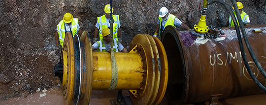
Insertion of the calibration pig DN 1400 into the section 1
Sources of water
The entire pipeline section tested by the company CEPS a.s. took in more than 78,000 m³ of water, which was taken from the stream Svídnice, the industrial reservoir Kyjická and river Ohře.
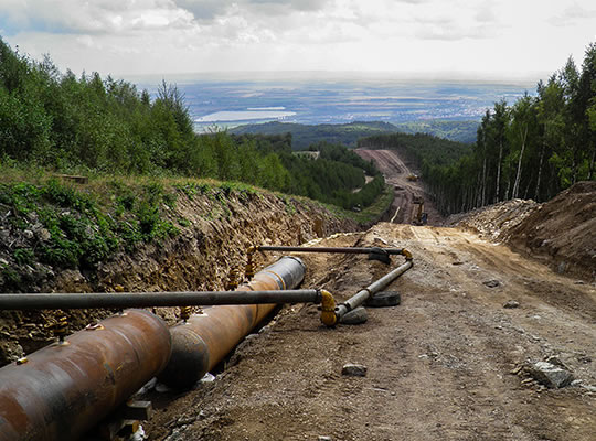
Gas pipeline GAZELLE DN 1400 in Krušné hory – passing of water up to higher located sections
After the tests were completed, the water was sent back into streams.
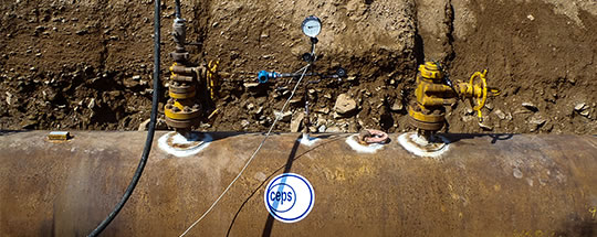
Monitoring of the position of the inlet pig
The monitoring of the position of the filling pig
In the mountainous sections was monitored the exact position of the inlet pig using hydrostatic pressure and longitudinal profile.
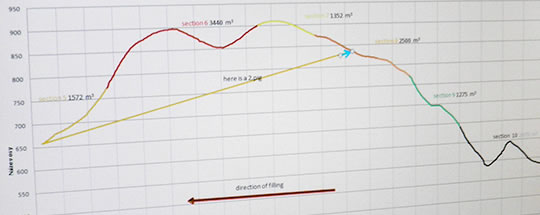
The gas pipeline DN 1400 GAZELLE – the longitudinal profile in Krušné hory – elevation all over the entire pipeline is 704 m
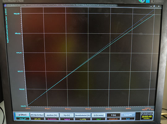
On the request of the future operator, the pipeline was loaded on limit of 110% of the actual yield strength. Nevertheless, it reached an average of only 10–30% of allowed deformation limits.
Calculation of the planned load
For each tested section has been calculated the planned load at the stress-test. Each pipe in gas pipeline has been checked with inspection documents, registered its melting and the actual yield strength, attributed the geodetic load and calculated loading pressure. After that was from those pipes chosen the weakest one in the section and the entire section was adjusted to this pipe. All this was done for the entire 52.5 km of the gas pipeline, pipe after pipe.
Stress-test in the section 9 in Krušné hory